As I started my cloud director (formerly vCloud director) journey, I am following a learn-by-doing approach as I want to set up my cloud director environment and blog about it while i am progressing and gaining more in depth knowledge in installing, configuring, managing and integrating vCD with the VMware ecosystem and later with third party solutions.
Today I want to share with you how to configure a NSX-T 3.0 one-arm load balancer for my 3-node Cloud director 10.1.1 cells.
I am assuming here that the NSX-T is fully deployed and functional and the 3-node vCD cells are deployed and hosted on VLAN-backed vDS port group. In addition, I assume that you already imported vCD and CA certificates into the NSX-T manager to be leveraged by the load balancer we’re creating.
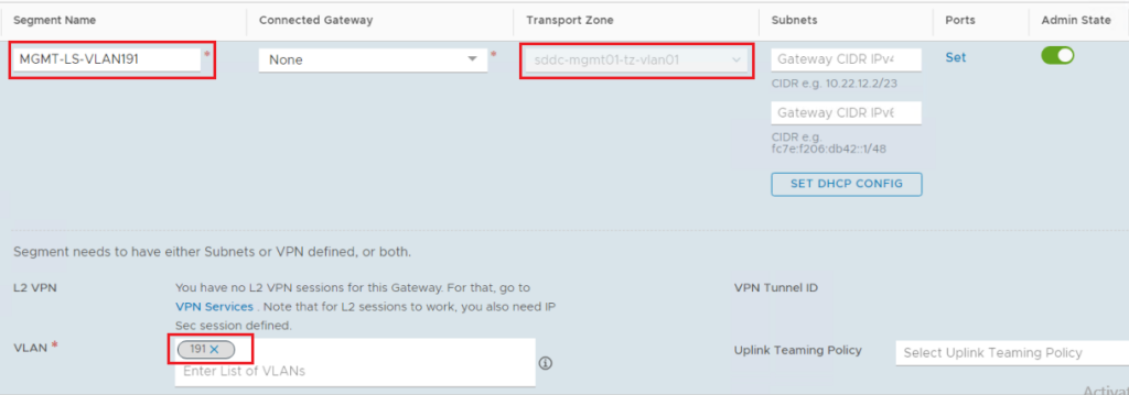
Step1: Create a VLAN-backed NSX-T Segment
Specify the segment name, the VLAN transport zone, and the VLAN ID. Note that this is the same VLAN ID as the one tagged on the vDS port group hosting the three vCD cells. The Tier-1 gateway service interface will connect to this VLAN.
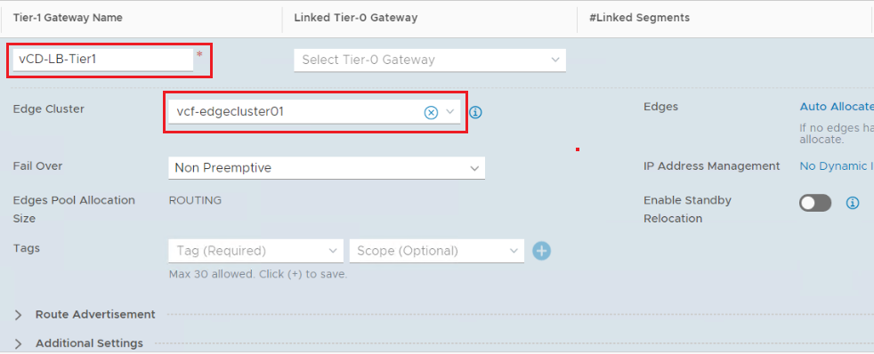
Step2: Create a Tier-1 Gateway
Instantiate the Tier-1 Gateway on an Edge Cluster as this Tier-1 Gateway will host load balancer stateful services. Don’t connect the Tier-1 gateway to the Tier-0 gateway as this Tier-1 Gateway will act as Standalone gateway.
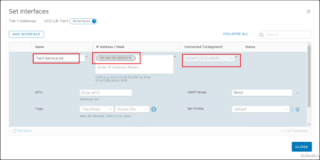
Step3: Add a Tier-1 Gateway Service Interface
Add Tier-1 gateway service interface and connect it to the VLAN segment we created earlier. The IP address of this interface will be on the same subnet as the vCD cells.
Step 4: Add a Default Static Route to the Tier-1 Gateway
Here we need to specify a default route where the next hop will be the physical router VLAN gateway interface.
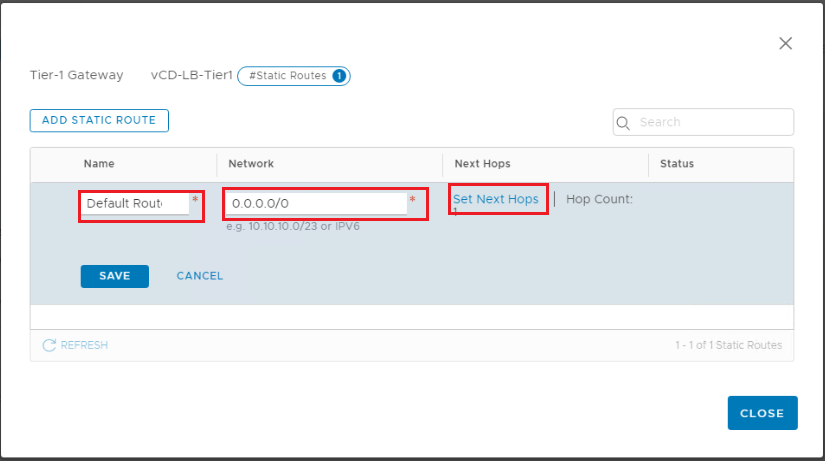
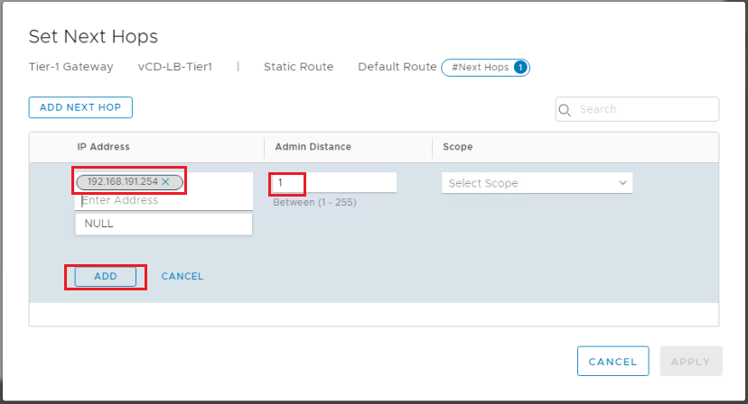
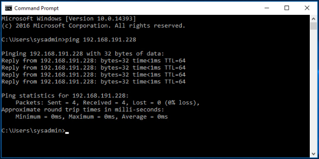
Verify and make sure the Tier-1 Gateway Service Interface is reachable from the physical environment.
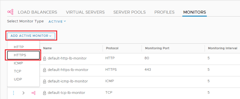
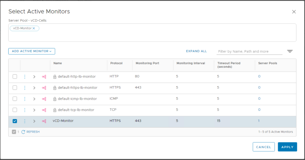
Step 5: Add LB monitor
Navigate to Networking > Load Balancing > Monitors > Add Active Monitor HTTPs.
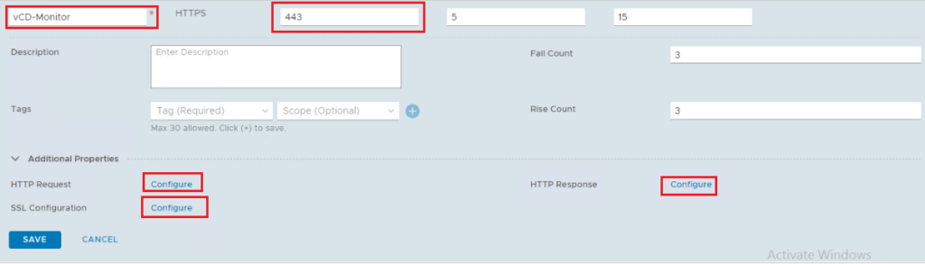
Monitor Details:
Protocol: HTTPs
Monitoring port: 443
Default timers
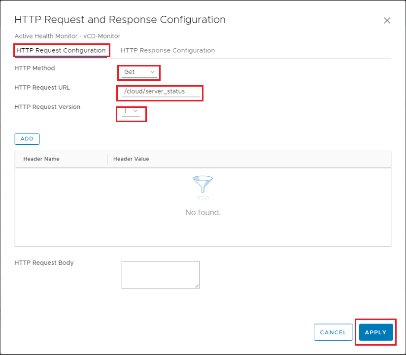
HTTP Request Configuration: GET /cloud/server_status, HTTP Request Version: 1
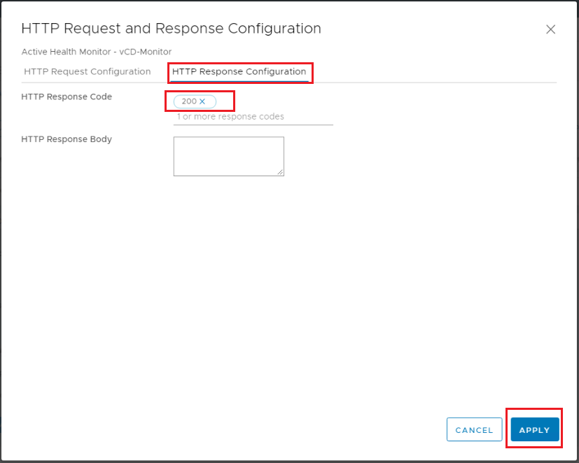
When using NSX-T 2.5 – HTTP Response Configuration: HTTP response body: Service is up. When using NSX-T 3.x – HTTP Response Configuration: HTTP response code: 200.
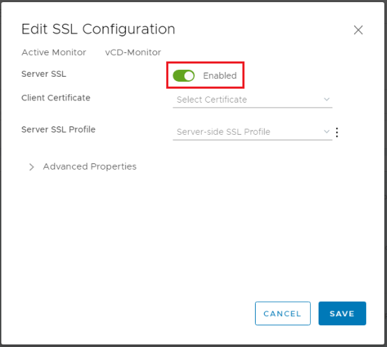
SSL Configuration: Enabled, Client Certificate: None
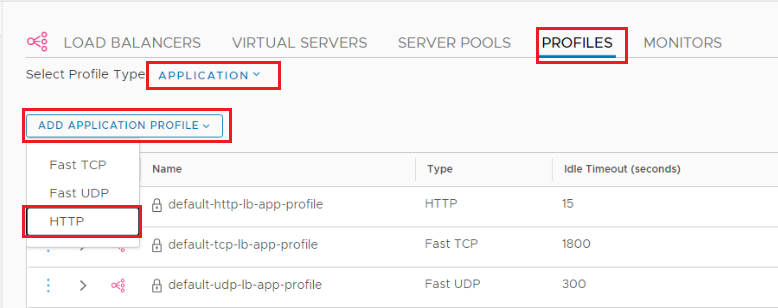
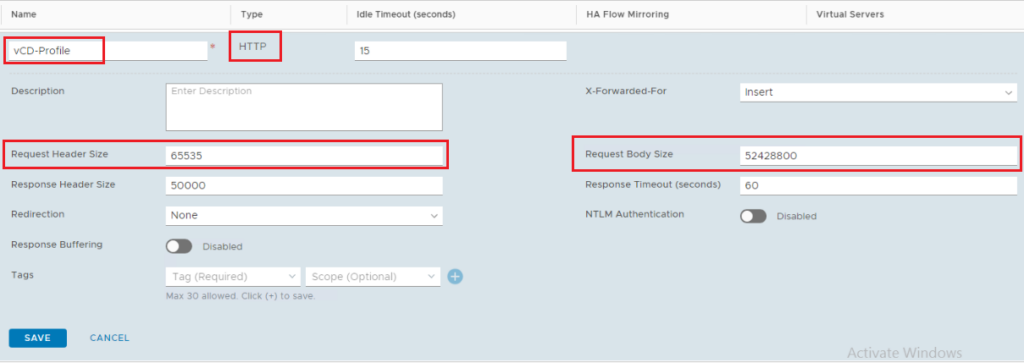
Step 5: Add Application Profile
Navigate to Networking > Load Balancing > Profiles > Add Application Profile > HTTP.
Application Profile Details:
Request Header Size: 65535
Request Body Size: 52428800
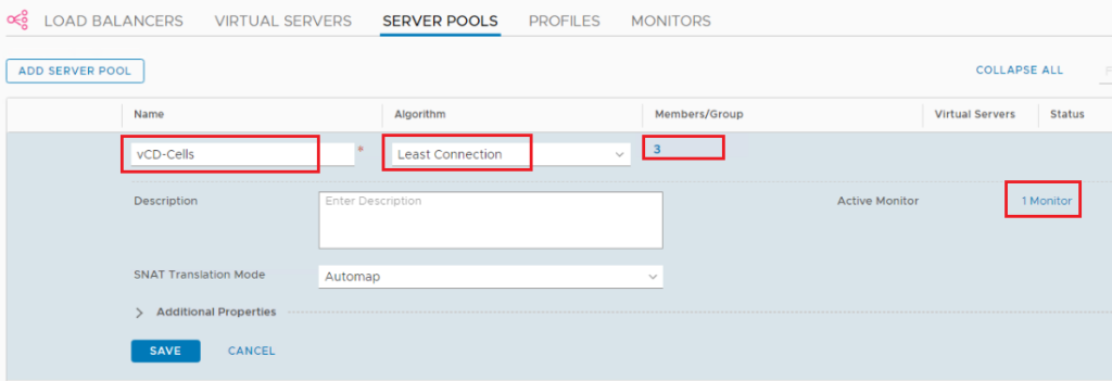
Step 6: Add Server Pools
Navigate to Networking > Load Balancing > Server Pools > Add Server Pool.
Algorithm: Least Connection
Active Monitor: the monitor we created before
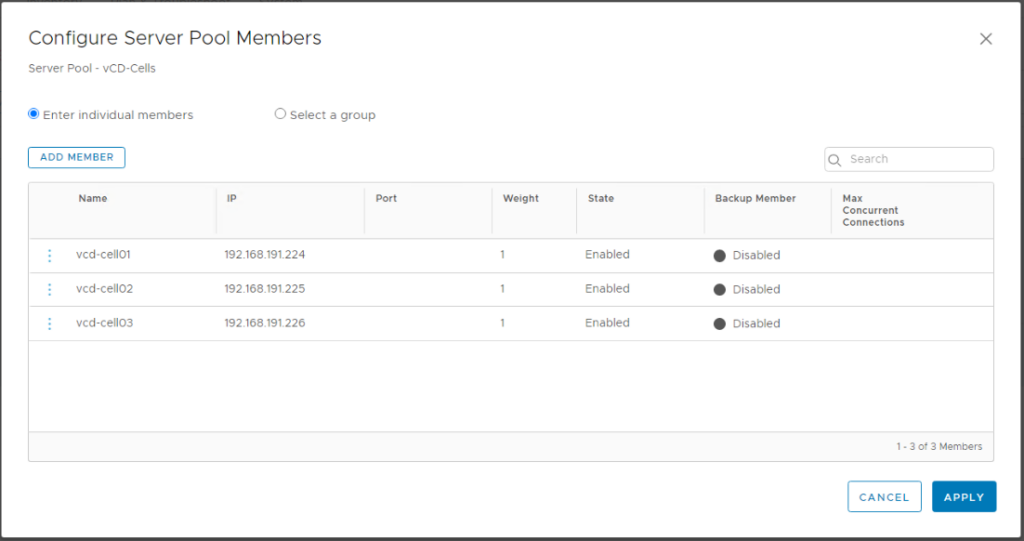
Select members: Enter individual members (do not enter port as we will reuse the pool for multiple ports)
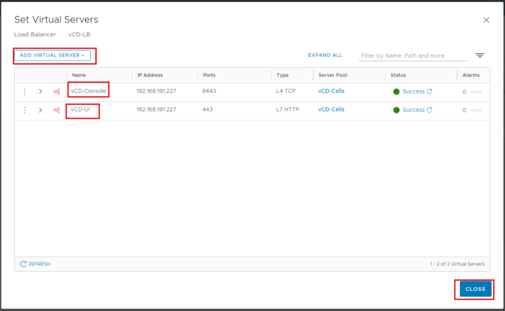
Step 7: Add Virtual Servers
We will add two virtual servers. One for UI/API and another for VM Remote Console connections. The same IP address will be used for both but with different Ports (443 vs 8443).
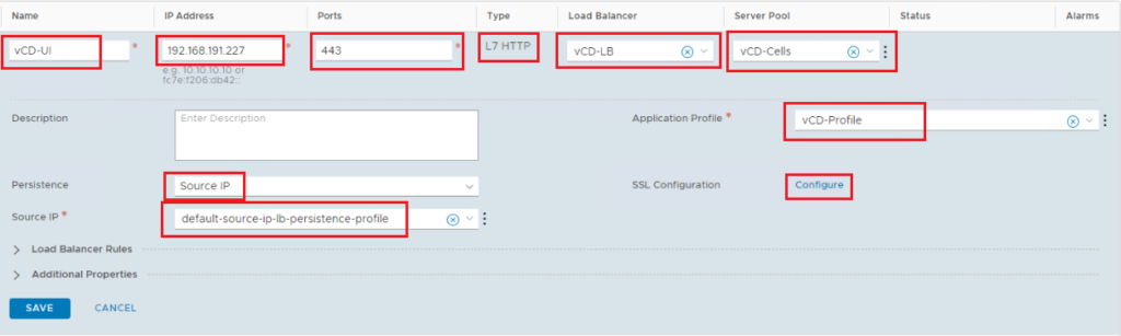
vCloud UI Virtual Server:
Add virtual server: L7 HTTP
Ports: 443
Server Pool: the one we created before
Application Profile: the one we created before
Persistence: default-source-ip-lb-persistence-profile
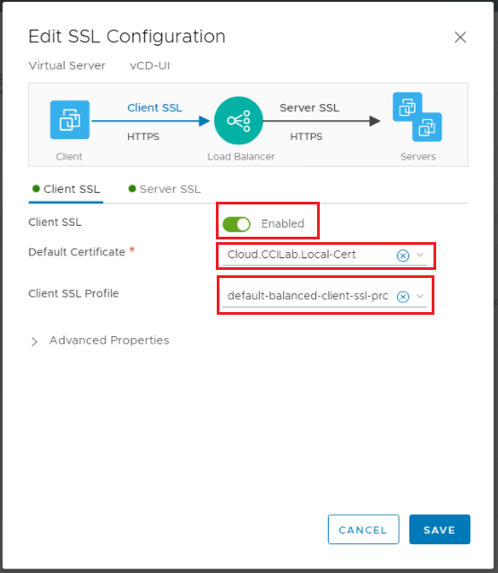
SSL Configuration: Client SSL: Enabled, Default Certificate: the one we imported before, Client SSL Profile: default-balanced-client-ssl-profile
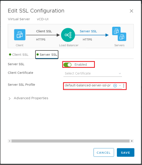
Server SSL: Enabled, Client Certificate: None, Server SSL Profile: default-balanced-client-ssl-profile
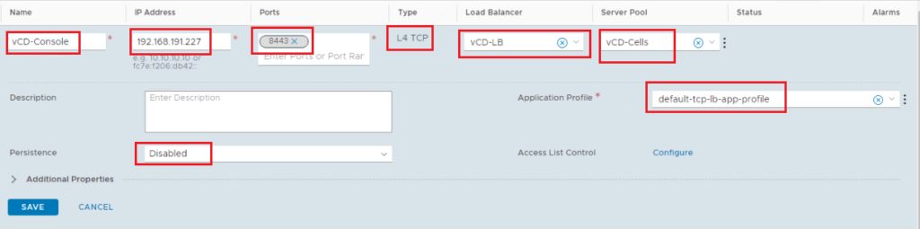
vCloud Console Virtual Server:
Add virtual server: L4 TCP
Ports: 8443
Server Pool: the one we created before
Application Profile: default-tcp-lb-app-profile
Persistence: disabled
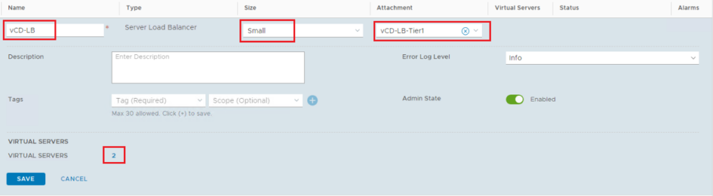
Step 8: Create Load Balancer
Here we will create the Load balancer instance on Tier-1 gateway and associate the virtual servers we already created with it.
Navigate to Networking > Load Balancing > Load Balancers > Add Load Balancer
Size: small
Tier 1 Gateway
Add Virtual Servers: add the 2 virtual servers created in the previous step.
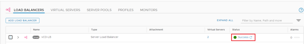
Make sure the status of the load balancer shows as Success.
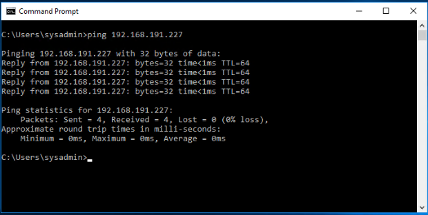
Verify that the load balancer IP address is reachable from the physical network.
Now you can change the public URLs on vCD and validate the access via the load balancer if it is working.
I Hope this post was informative,
Many thanks for reading,
 (3 votes, average: 5.00 out of 5)
3 thoughts
Comments are closed.