
In this post, I am going to demonstrate how NSX-T helps isolate routing domains by configuring NSX-T 3.x VRF lite.
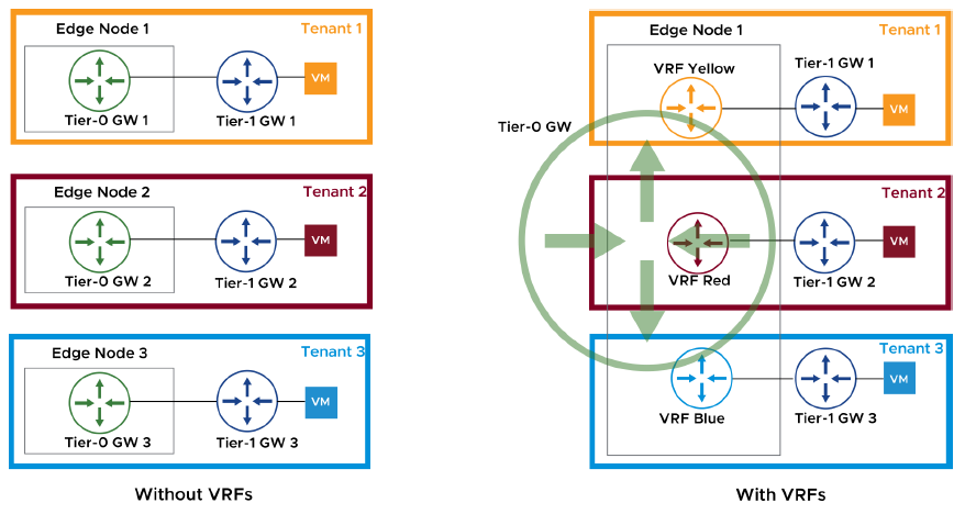
Virtual Routing and Forwarding (VRF) is a routing technology that allow the coexistence of multiple routing instances in one routing device. Independent routing and forwarding tables are maintained for each instance.
With VRF-Lite, separation between tenants and applications does not require additional edges/Tier-0 gateways. VRF Lite provides logical routing isolation in NSX and spans it to external peer devices that support this technology. VRF Lite differs from other VRF implementations as it does not rely on MPLS and MP-BGP protocols running in the physical network. Same network addresses can be used in different VRFs.
A VRF Lite deployment has the following requirements:
– Deployed Tier-0 gateway (This is called as the default Tier-0 GW and acting as the parent gateway for the VRF gateways)
– External connectivity with a layer 3 peer
– Peer device that supports 802.1Q protocol (VLAN tagging)
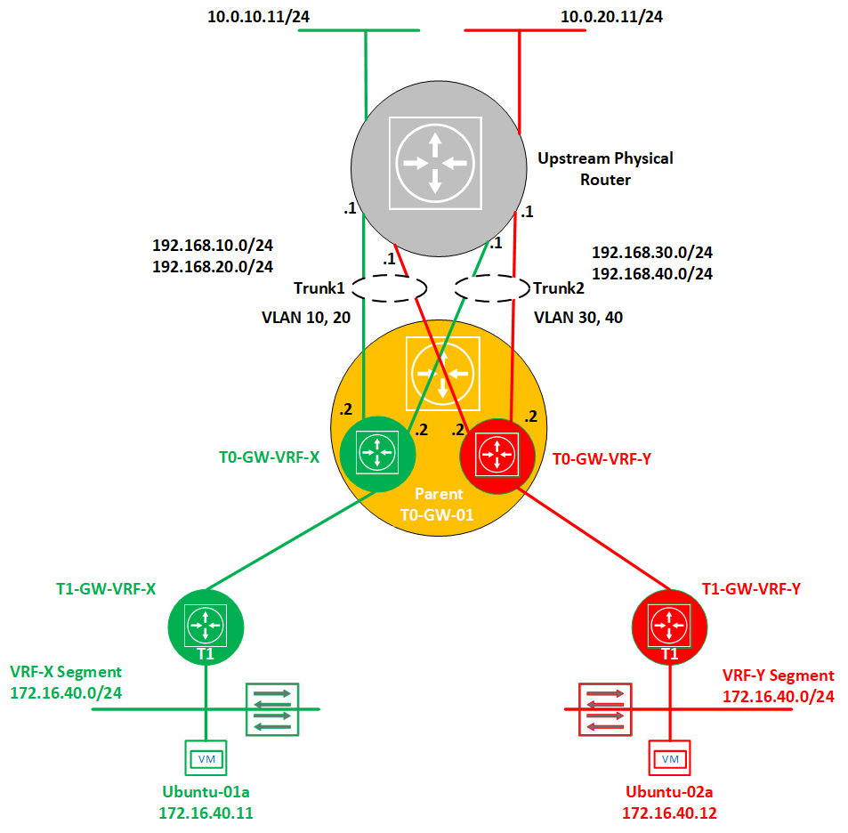
Now let’s have a look on the below topology that we will use to demonstrate VRF Lite configuration and end-to-end verification.
1- Deploy the default Tier-0 gateway
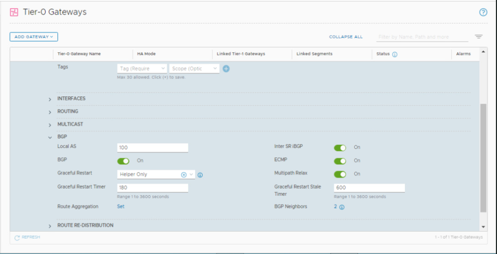
I am assuming here that a Tier-0 gateway is already deployed and BGP configured with the upstream physical network. VRF gateways inherit the parent Tier-0 GW global BGP configuration (Local AS, Graceful restart, Graceful restart timer, Graceful restart stale timer, Multipath relax). These parameters can only be changed in the default Tier-0 gateway.
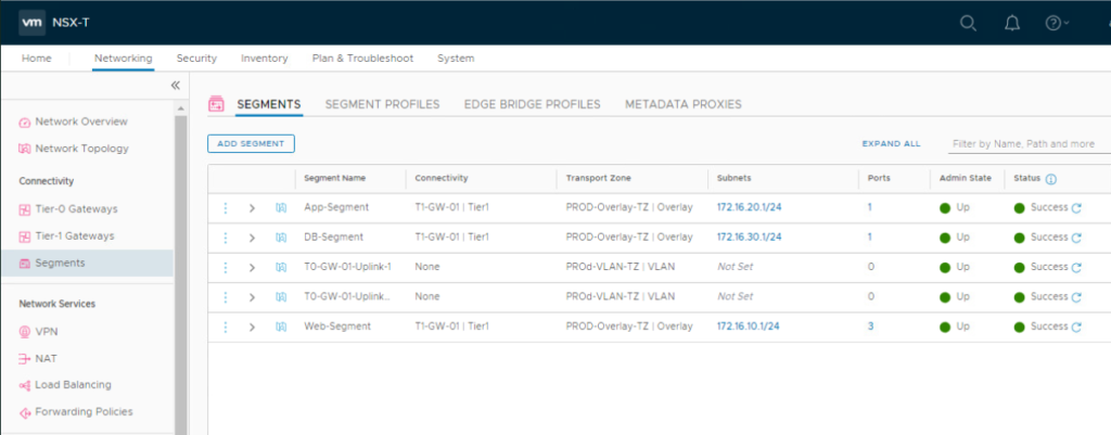
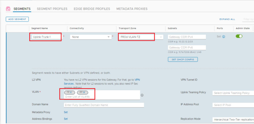
2- Create the Uplink TRUNK Segments
We need to create the uplink trunk segments that will be connected to the uplink interfaces of each VRF gateway. In the NSX UI, navigate to Networking > Connectivity > Segments > SEGMENTS. Click ADD SEGMENT.
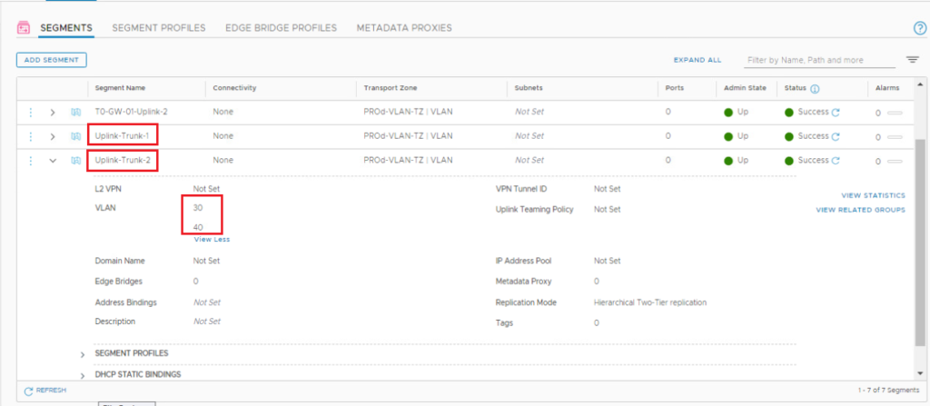
Repeat the same steps to add the second trunk segment in our topology with VLANs 30, and 40.
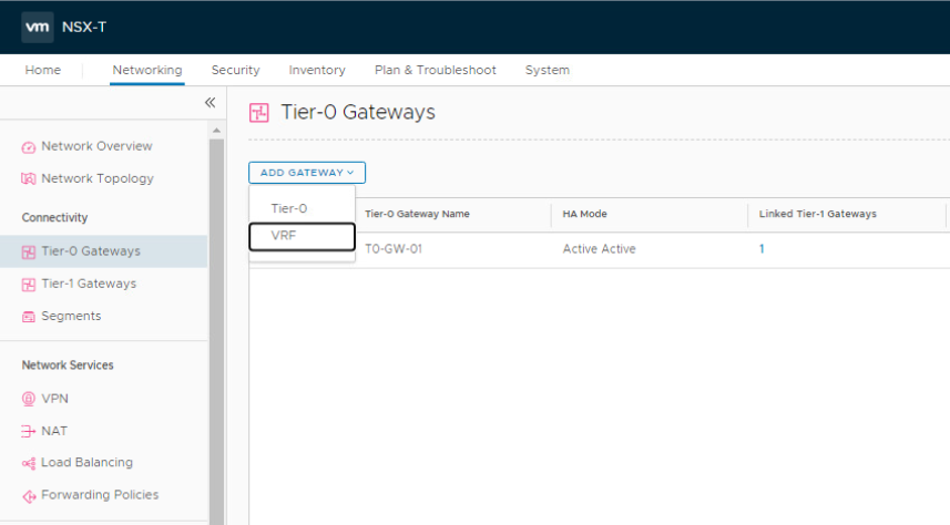
3- Deploy VRF-X gateway
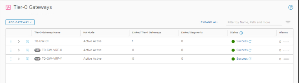
In the NSX UI, navigate to Networking > Connectivity > Tier-0 Gateways.
Click ADD GATEWAY and select VRF from the drop-down menu to deploy the first VRF gateway.
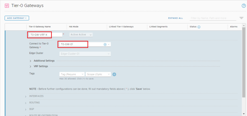
Fill in the name for VRF-X Tier-0 gateway and select the parent Tier-0 gateway. Click SAVE and click YES at the “Want to continue configuring this Tier-0 Gateway?”.
Repeat the same steps to add VRF-Y gateway.
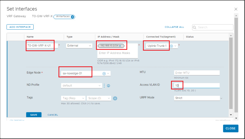
4- Add Uplink Interfaces to VRF-X gateway
Under VRF-X Tier-0 gateway, expand Interfaces and click Set.
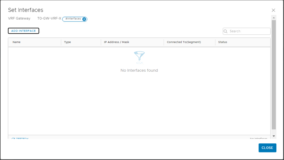
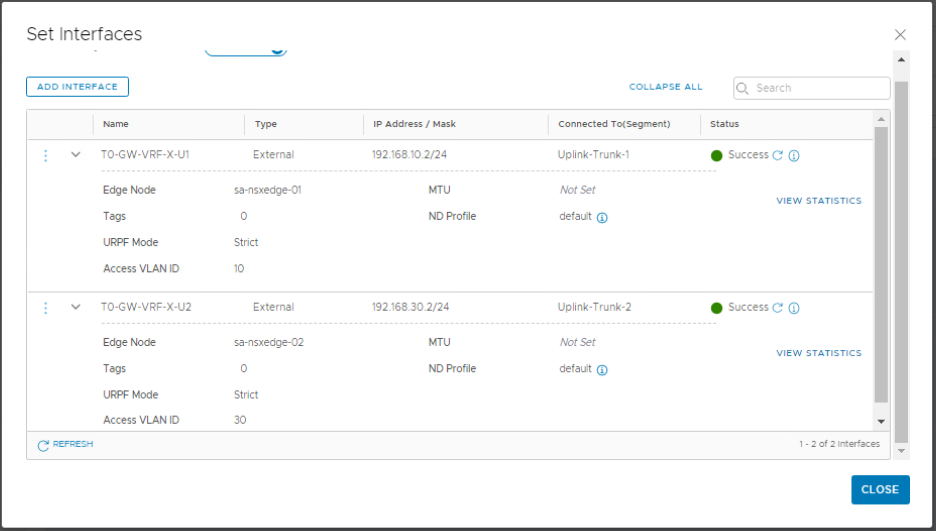
Click Add Interface and configure the first uplink interface for the VRF-X gateway. Note that we are connecting the VRF gateway uplinks to the trunk segments we created previously. Click Save.
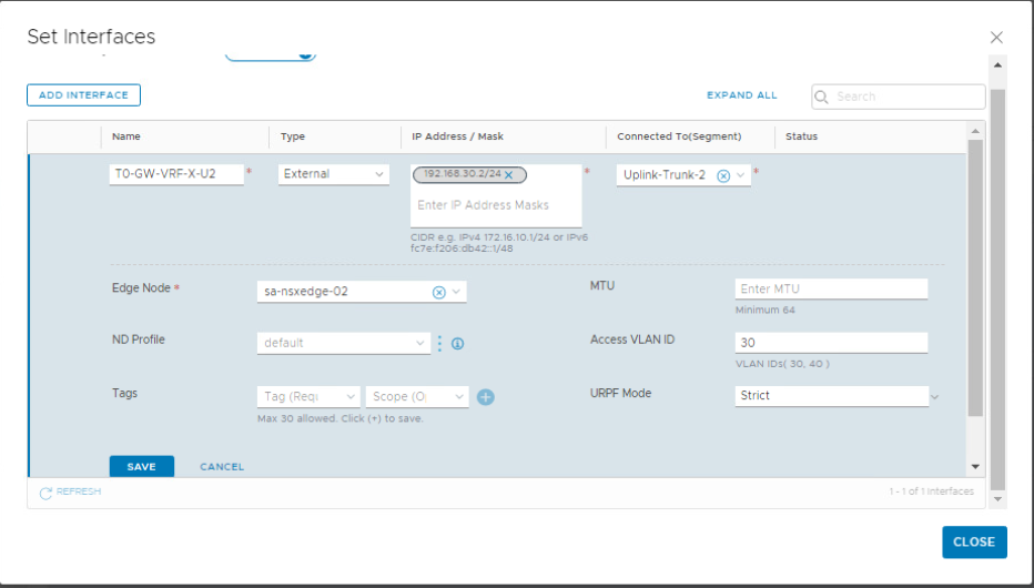
Add the second uplink interface for the VRF-X gateway.
Repeat the same steps to add the uplink interfaces to VRF-Y gateway.
5- Configure BGP for VRF-X gateway
Under VRF-X Tier-0 gateway, Click the expand button next to BGP. Turn on the BGP toggle and click SAVE.
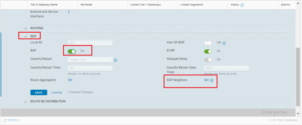
Click Set on the right of BGP Neighbors. When the Set BGP Neighbors window appears, click ADD BGP NEIGHBOR and set up the first peering with the upstream router.
Click Set, click ADD ROUTE FILTER, click ADD for the IPv4 address family, and click Apply.
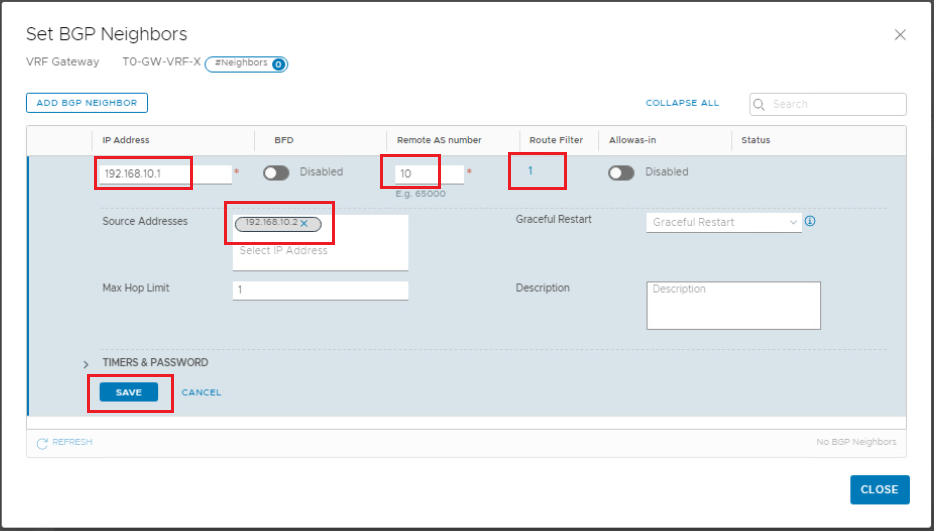
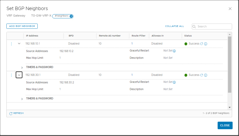
Click Save to finish configuring the first neighbor. Repeat the same steps to add the second BGP neighbor.
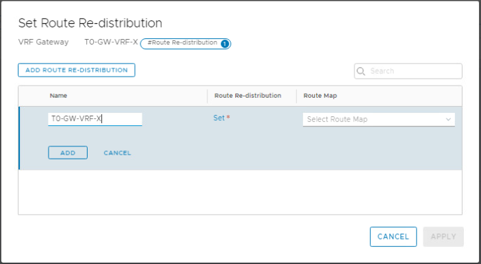
Under VRF-X gateway, scroll down to Route Redistribution and click Set.
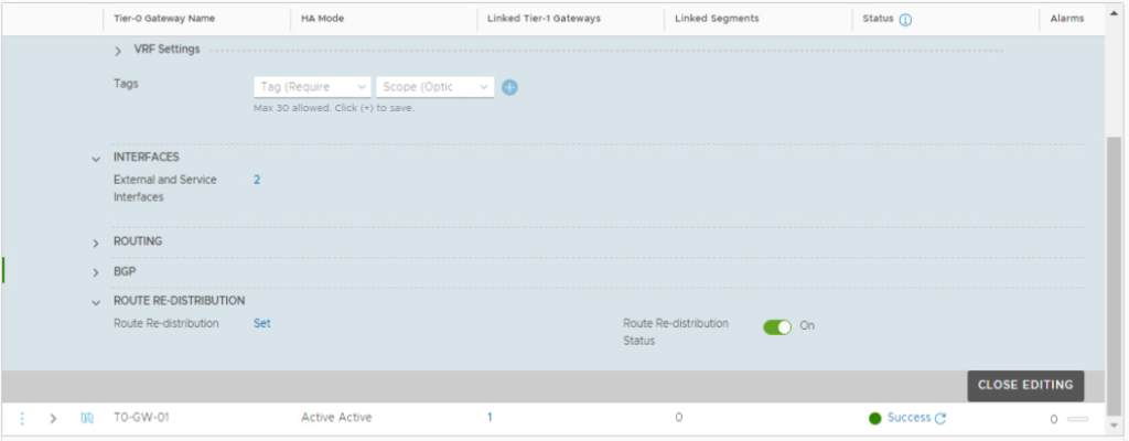
Click Add Route Re-distribution and provide a name and then click Set.
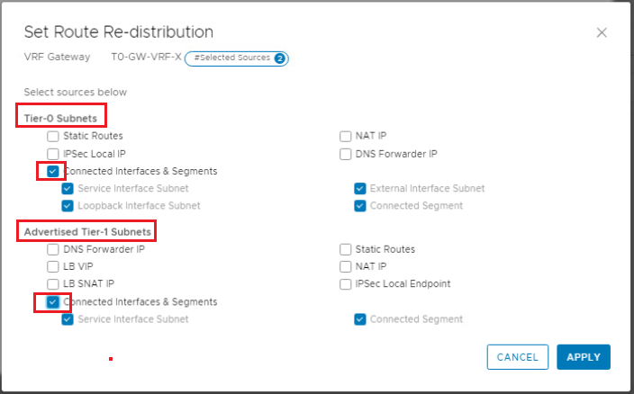
Enable re-distribution for Connected Interfaces & Segments under Tier-0 Subnets, and for Connected Interfaces and Segments under Advertised Tier-1 subnets.
Repeat the same steps to configure BGP and route re-distribution for VRF-Y gateway.
6- Deploy and Connect VRF-X Tier-1 Gateway to VRF-X Tier-0 Gateway
Here we will deploy a Tier-1 gateway for each VRF and link it to the corresponding VRF Tier-0 gateway.
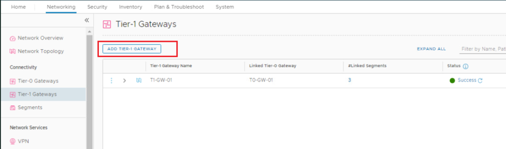
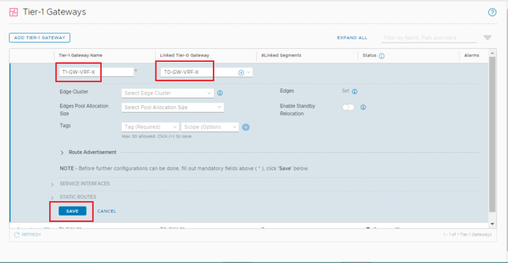
In the NSX UI, navigate to Networking > Connectivity > Tier-1 Gateways. Click ADD TIER-1 GATEWAY to add the Tier-1 gateway connected to VRF-X.
Enter a name for the Tier-1 gateway and link it to VRF-X Tier-0 gateway. Click Save.
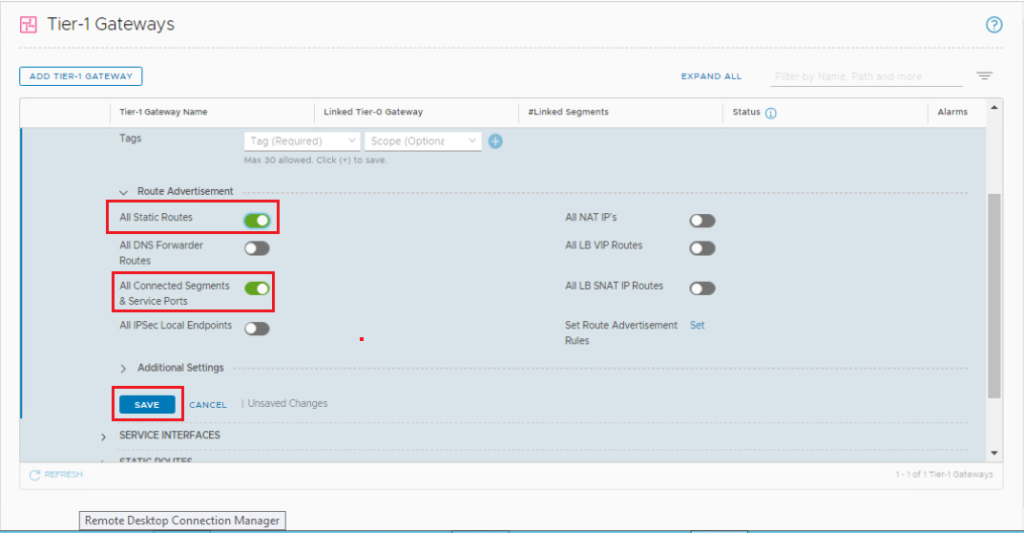
Scroll down, expand Route Advertisement, toggle both All static routes and All connected segments and service ports and click Save.
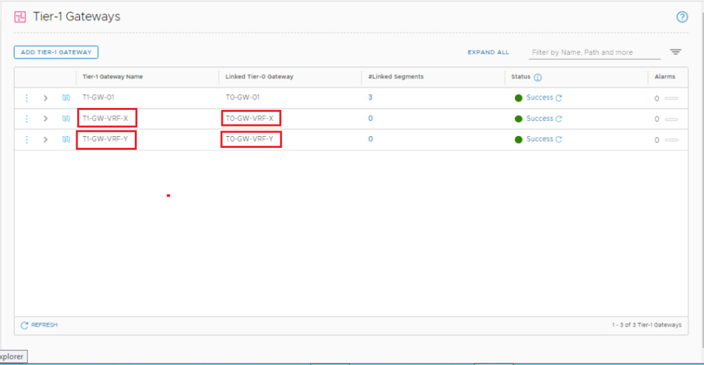
Repeat the same steps to deploy VRF-Y Tier-1 gateway & link it to VRF-Y Tier-0 gateway.
7- Create and Connect Segments to the Tier-1 Gateways
We will create one segment for each VRF and connect it to the corresponding Tier-1 gateway. Each segment uses the same subnet in our topology to verify the routing isolation between VRFs.
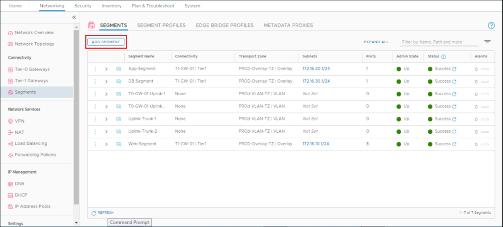
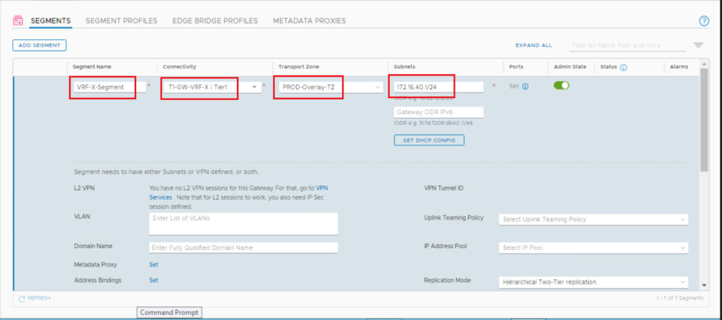
Let’s first create a segment for VRF-X. In the NSX UI, navigate to Networking > Connectivity > Segments. Click ADD SEGMENT and configure the segment.
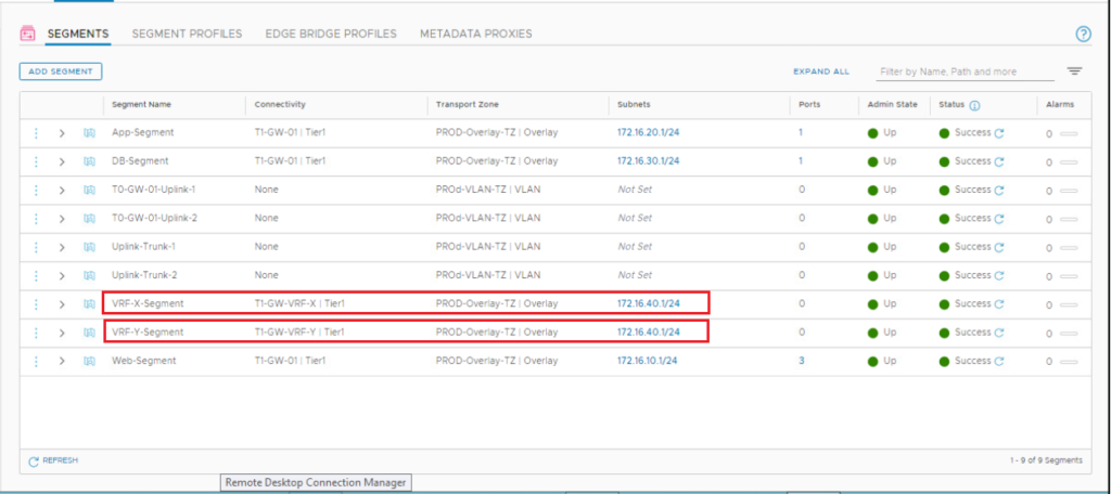
Repeat the same steps to create VRF-Y overlay segment.
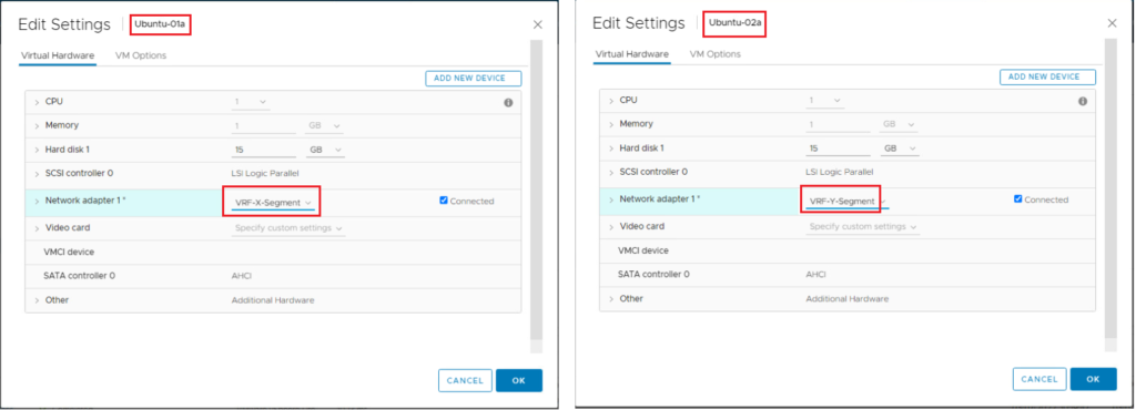
8- Attach VMs to Segments on Each VRF
We will attach an Ubuntu VM to the created segment for each VRF.
9- Test the VRF End-to-End Connectivity
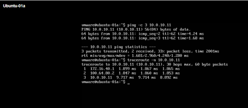
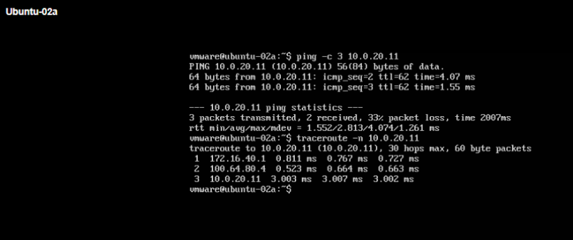
We will test the connectivity from VMs, which are connected to VRF segments, to the remote networks preconfigured in each VRF on the upstream physical router.
10- Verify the Routing Isolation Between VRFs
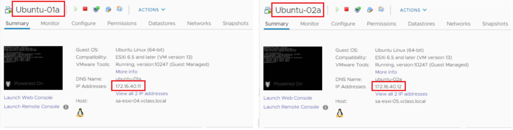
Now we will verify the lack of connectivity between VMs that are connected to segments in different VRFs although they are using the same 172.16.40.0/24 subnet (See below).
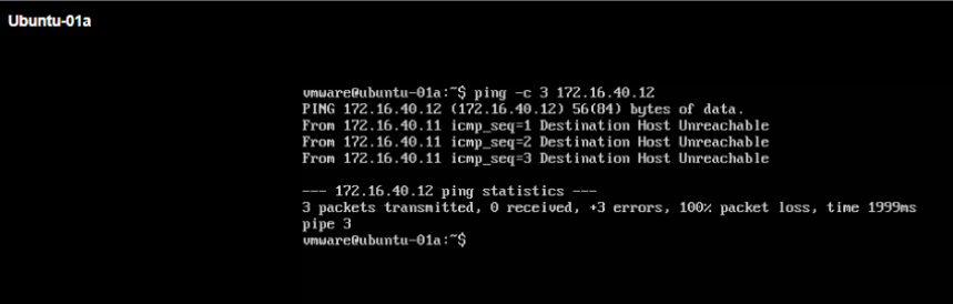
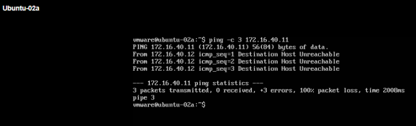
Below we will try to ping between Ubuntu-01a VM in VRF-X and Ubuntu-02a in VRF-Y (Ping should NOT be successful in both directions).
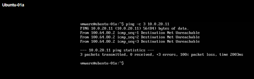
Below we will try to ping from Ubuntu-01a VM in VRF-X to 10.0.20.0/24 remote network IP in VRF-Y (Ping should NOT be successful).
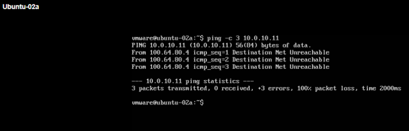
Finally we will try to ping from Ubuntu-02a VM in VRF-Y to 10.0.10.0/24 remote network IP in VRF-X (Ping should NOT be successful).
Thanks for your time reading this lengthy post,
I hope it was informative,
 (1 votes, average: 5.00 out of 5)